
Simple bolt pattern — finite element approach
Simple Bolt Pattern example (FEA - Finite Element)
Consider the simple bolt pattern problem (the same problem as shown in the classical method of bolt pattern analysis):
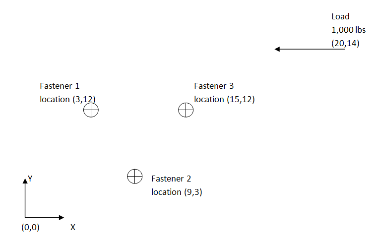
The problem at hand is to determine the shear forces in each of the fasteners given the applied load. The model can be represented simply with an RBE2 element (infinitely stiff Rigid Body Element) shown in magenta and grounded CBUSH elements (blue) representing each fastener.
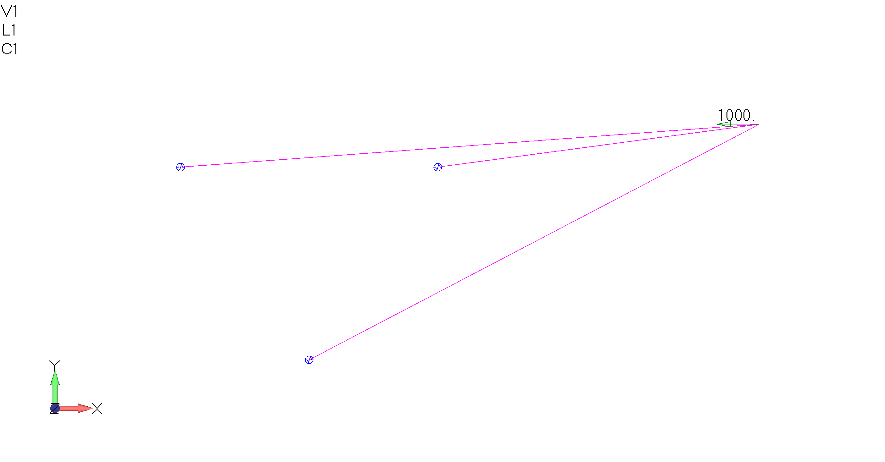
The above figure is the graphical representation of the following NASTRAN bulk data.
|
FORCE,1,1,0,1,-1000,0,0, PBUSH,3,K,1.+7,1.+7,1.+7 GRID,1,0,29.99792,14.00002,0,0 GRID,2,0,3,12,0,0 GRID,3,0,9,3,0,0 GRID,4,0,15,12,0,0 GRID,5,0,3,12,0,0,123456 GRID,6,0,9,3,0,0,123456 GRID,7,0,15,12,0,0,123456 RBE2,1,1,123456,3,4,2 CBUSH,2,3,2,5,,,,0 CBUSH,3,3,3,6,,,,0 CBUSH,4,3,4,7,,,,0 |
When analyzed the following fastener forces are determined:
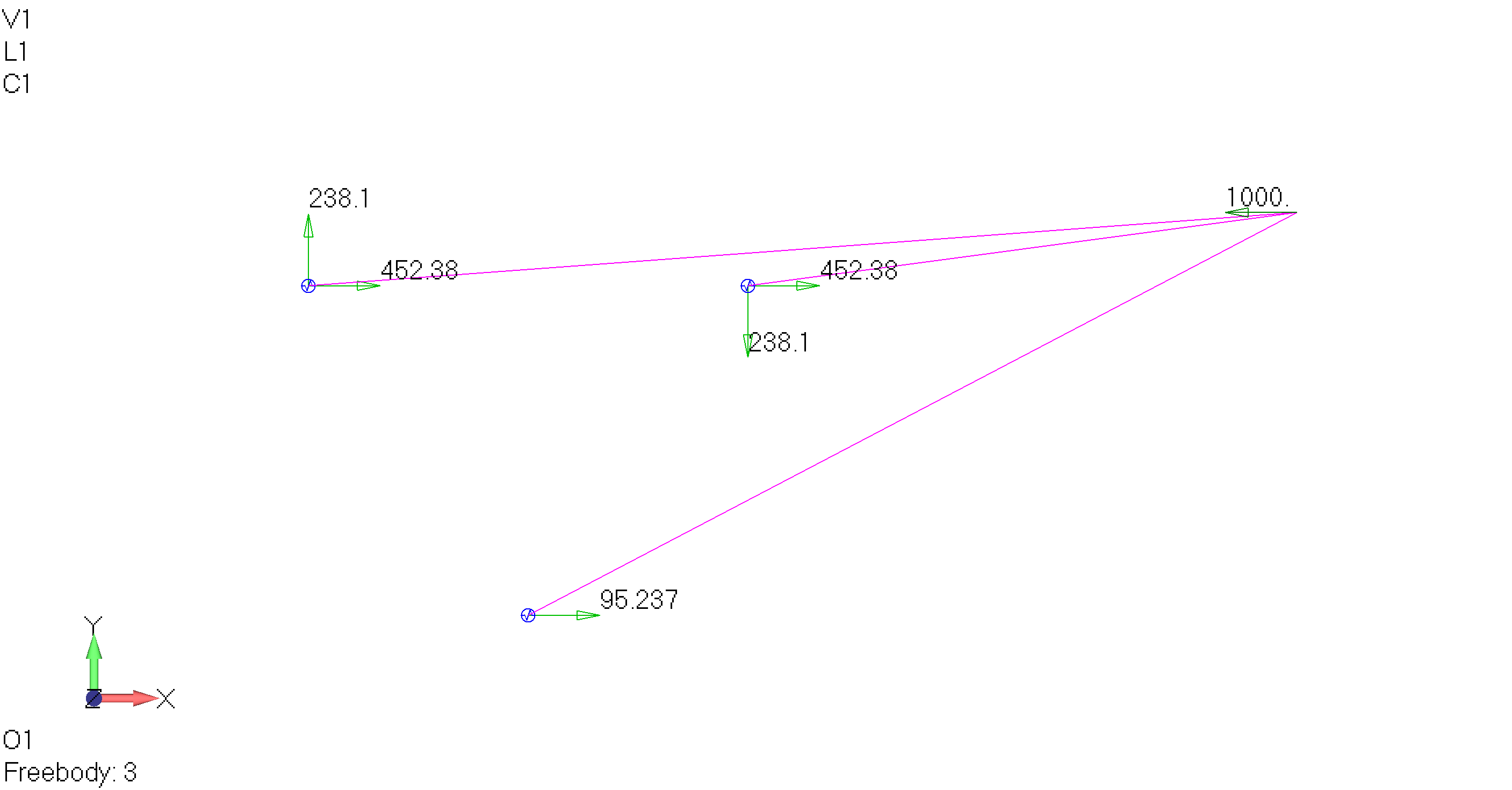
These results correlate well with the results from the classical method of bolt pattern analysis.
OK, now that we have the basics, go ahead and give it a try. You can use this handy bolt pattern load calculator to check your work.
As discussed in the Simple Bolt Pattern (classical method) the sum of the fastener reactions should be equal and opposite to the applied load. This means static equilibrium is maintained. This is also true with CAE and it is a good practice to do a "sanity check" and ask yourself do my FEA results make sense?
Foundations articles are pragmatic examples, not training in structural analysis and not a recommendation for how a particular analysis should be done; each real situation is unique. All Foundations topics · Ask about a project